This post is a multi-part post, the 1st part covers the 2 different models that are widely deployed, initial configuration for the BNG with dynamic templates/service policy maps and the 2nd part will cover the shared radius infrastructure and retail ISP#1 own DHCP server instead of using the wholesale BNG to handle the DHCP requests.
BNG wholesale is an interesting concept I’ve wanted to write about for some time, so lets build a lab together to create a scenario where we have 2 retail ISPs (diagrams may show 2 or more for examples) who are only based in specific regions but want to branch out further and start providing services to other parts of the country on top of an existing access network. There are so many moving parts to this area that I need to mention this is not a blog about best practices, what technologies/protocols to use and how to perform wholesale services on top of a BNG infrastructure, this is aimed more towards those who are interested in the concept and just want to see some random guys thought about how this would work from a high level overview.
Take a look at this diagram below and we’ll discuss each part in small detail before going into more depth with how we will set up the lab. Note that while writing this blog, I’m actually setting up the lab first time so we will learn together, think of this post as a learn-together style post, by all means I am not an expert in this area.
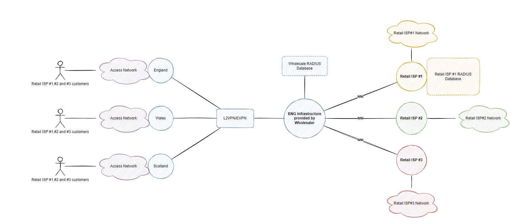
Lets run through this diagram together from right to left. There are 3 retail ISPs in our scenario which want to provide services across England, Wales and Scotland (multiple towns within these countries for example) but they don’t have the capacity or money to build their own access network within these towns. However the wholesaler who can provide access to these regions/countries by handing off an NNI within a specific DC in the country of the retail ISP core network and carry back ethernet frames from the access network (or present the customers with Layer 3 handoff so the retail provider doesn’t have to deal with VLAN tags such as QinQ).
These ethernet frames can be carried for each retail ISP from the access network whether it be the wholesalers own access network (or another access network provider), the interesting thing here is that the BNG wholesale model can be responsible for authenticating each retail ISP subscriber and perform basic functions such as rate limiting (that adhere to the retail ISP customer speed packages) or completely handle the layer 3 aspect so that the retail ISP doesn’t have to run DHCP, RADIUS and other services.
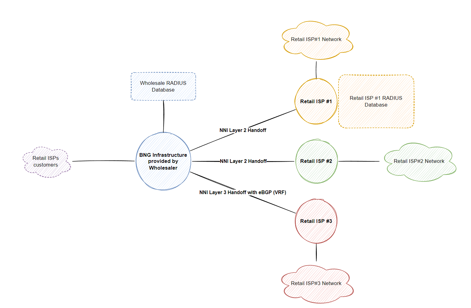
Layer 2 NNI Model
Typically in this type of design, each subscriber is configured a unique VLAN ID to ensure subscriber traffic is properly segregated on the access network and that customers can not communicate with each other. However this leaves us a total of 4096 customers (if your vendor doesn’t reserve the first and last VLAN) so then we introduce QinQ (802.1AD, double tagging, S-VLAN and C-VLAN, whatever you want to call it) to scale the amount of customers for each retailer ISP. In the below example, I’ve assigned S-VLAN 10-19 to ISP#1, S-VLAN 20-29 to ISP#2, S-VLAN 30-39 to ISP#3. Obviously you’d scale these numbers up based on the requirement and planned growth (eg. 100 S-VLANs per retail ISP allows 100*4094 (400+k) VLANs/aka retail customers across the entire network for that single retail ISP, however only in 100 locations within the nation-wide network, hence why you need better planning than my numbers, just a demonstration remember!)
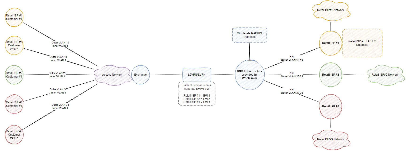
Depending on the overlay technology used to carry the ethernet frames back to the retail ISP such as L2TP, VPWS/VPLS or PBB-EVPN, seperation is key and implementing best practices related to the technology is important, you want to ensure broadcast traffic doesn’t go over your whole L2VPN network and only to the relevant BNGs that serve that retail ISP.
The retail ISP may create p2p sub-interfaces on a small scale but then they might also want to implement their own BNG functionality to map C and S vlans when egress traffic returns via the wholesalers NNI, however at that point you could just hand over an NNI directly from your upstream router if you are not terminating the services directly on a BNG (if they don’t want to use your wholesale shared RADIUS for authenticating/authorizing their own subscribers also, you can just forward the traffic to the retail ISP and treat your BNG like a PE router, connecting to the customer, a CE router).
Since this post focuses on Cisco IOS-XR (XRv9K), we either have the option with passing L2TP when using PPP to the customer to handle the authentication/authorization. When using IPoE, we will have to terminate the sessions on the wholesaler BNG and can’t actually pass the ethernet frame to the retail ISP (as far as I know of, please correct me if I am wrong with XRv9K, technically in production you could probably bridge the subscriber interface on the BNG and the layer 2 NNI within the same bridge domain however XRv9K doesn’t support l2vpn bridges (7.3.1)) so this restricts us to only tunnel from the BNG to the retail ISP using L2TP. The problem with this is that when we terminate the session on the wholesaler BNG, we now handle the AAA functionality so the only option we have is to redirect the traffic into the retail ISP VRF and send a 2nd RADIUS access-request to the customers server if they would like to handle further attributes which can be merged together with the attributes returned from the shared-radius infrastructure (typically holds the User-Name and VRF to redirect the subscriber to the correct retail ISP).
Layer 3 NNI model
Providing a layer 3 model requires us (the wholesale) to run additional protocols/services to provide not only authentication/authorization but also layer 3 connectivity (IP addresses via DHCP/PPPoE) if they don’t want to host it themselves. Otherwise within the policy framework configured for that specific retail ISP on the BNGs, DHCP requests can easily be relayed/proxied to the retail customers own DHCP server (or PPPoE server if running PPPoE).
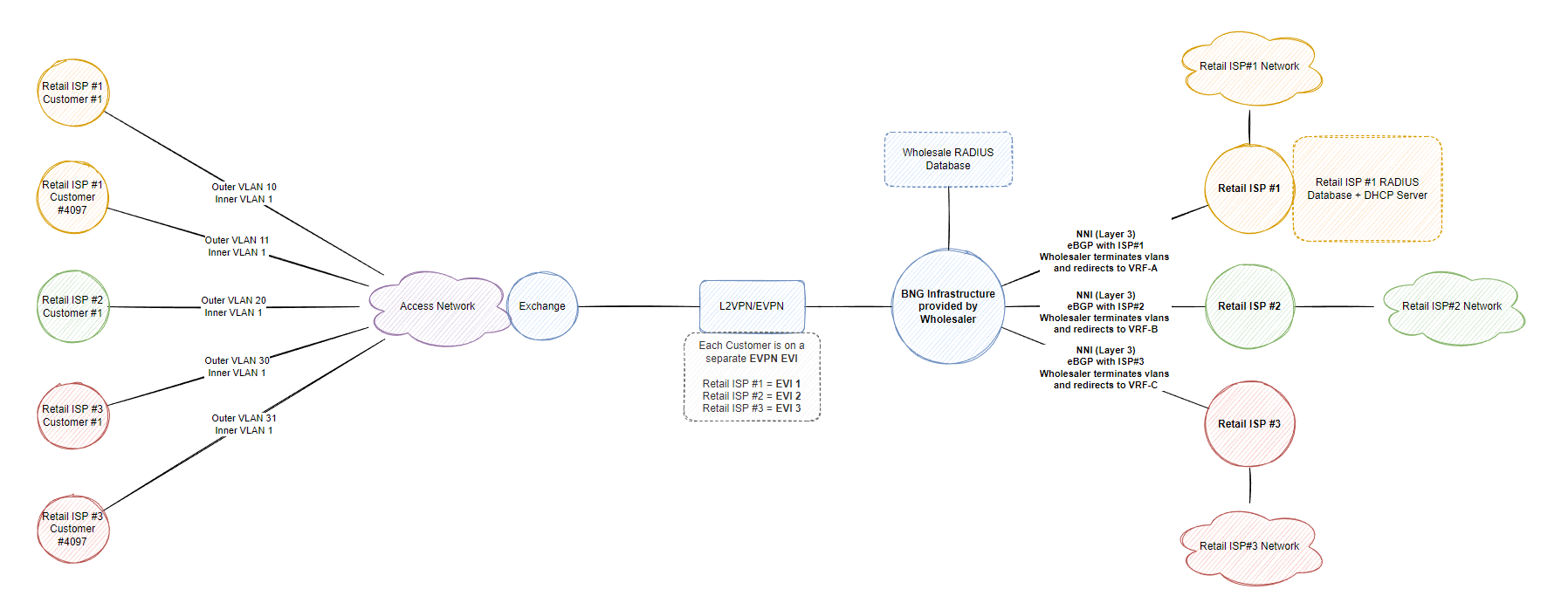
The traffic carried throughout the wholesale network doesn’t change, we still carry back ethernet frames back to the BNGs but then store the layer 3 information on the BNG within a separate routing domain (aka VRF) and advertise via BGP the block they configure, whether it be a public ip block or private CGN block, retail ISP #1 may run public IPv4 (and v6) addresses whereas retail ISP #2 may send a default route via BGP to VRF-B which takes the ISP #2 subscriber traffic to a CGN. At this point, the wholesaler doesn’t care what happens with the traffic as long as they can terminate the subscriber, authenticate/authorize them and be able to send traffic back out to the retail ISP subscriber then everything is working. At this point we can either store the relevant VRF information within the shared radius database if the retail ISP choses to not use their own database or statically configure it under a dynamic template on IOS-XR like this:
dynamic-template
 type ipsubscriber DT_IPOE_ISP1
  vrf ISP1
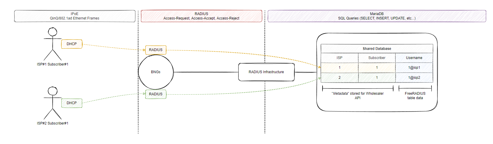
In our lab, we will attempt to provide services for 2 retail ISPs, a layer 3 NNI for ISP#1 who wants to use the shared radius database and a layer 3 NNI for ISP#2 who will also use the shared radius database but run their own DHCP server. Note that when I say “shared”, there should be some form of proxy in between the retail ISP and the database itself, this will be a HTTP API that only allows each customer to interact with their own data they have created (FreeRADIUS + MariaDB database). FreeRADIUS doesn’t have way to ensure the database is split between customers in this scenario (eg. ISP#1 has its own database table) so we will use a suffix to hold the customers subscribers and only allow their relevant API route (eg. POST/DELETE/GET https://wholesale.example.com/api/v1/subscribers) to perform the functions related to this retailer ISP. My thought is in this scenario you’d probably build a better API with authentication and a permission framework to only ensure that the specific ISP is only allowed to amend their own data or customize the SQL modules in FreeRADIUS to facilitate this type of workflow. The reason I am not configuring a layer 2 NNI is because I don’t want to deal with PPPoE/L2TP and LAC/LNS :-)
Basic workflow for this will look something along these lines:
Initial Lab in EVE-NG
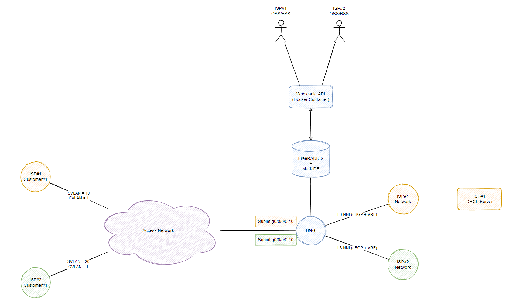
All final configurations can be found here: Configurations
Building the Lab together
As mentioned, writing this sentence I have not got a fully working lab which is why I want to take this opportunity to build the lab and document the process here on this post. Firstly I need to be able to replicate a QinQ/double tagged customer which I’ll use a CSR1000V with 2 sub-interfaces in separate VRFs to replicate 2 subscribers and just perform the authentication against MAC address as the username (typically you’d deploy something like option-82 for DHCPv4 and option-37 for DHCPv6). These sub-interfaces will just act like subscribers for both retail ISPs.
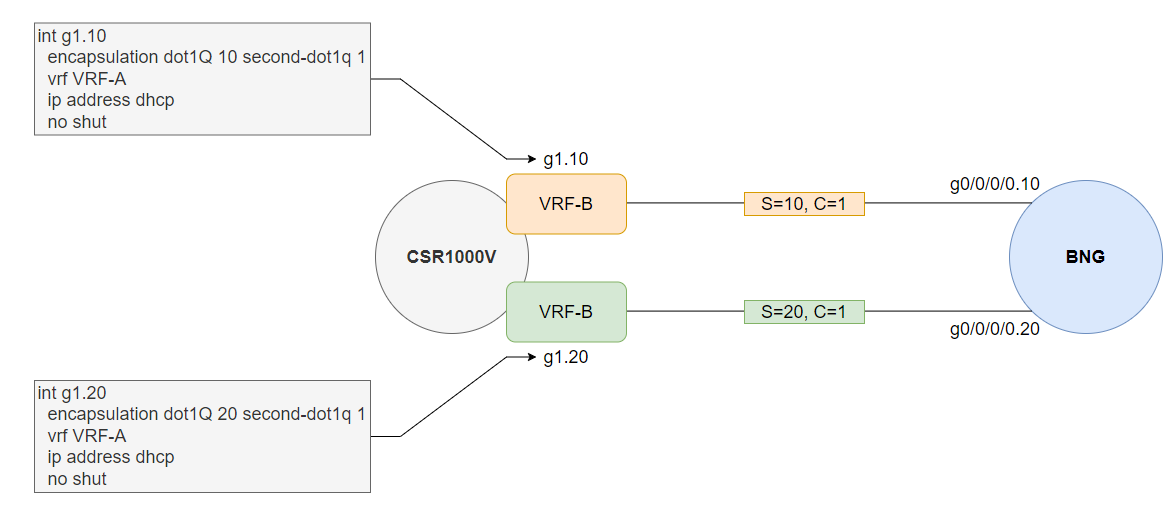
Currently I am using XRv9K to act as the BNG, I’ll create a sub-interface per retail ISP which matches the relevant S+C VLAN combo, you can match any C VLAN in production which would be preferred since the S-VLAN would always be for that retail ISP and we don’t actually care about the C vlan from the BNG perspective. We will also tie a subscriber policy to each sub interface, retail ISP#1 called CSPM_IPOE_ISP1 and retail ISP#2 called CSPM_IPOE_ISP2. Naming is just based on the following
- CSPM = Customer Service Policy Map
- IPOE = IP over Ethernet service (PPPoE could be something like CSPM_PPPOE_ISP1)
- ISP1 = Retail ISP #1….
The reason for using a separate policy map is that we would use a different AAA format to match ISP#1 with the suffix of @isp1 which should be presented in DHCP option-82, however I will skip this part and just purely authenticate based on MAC address… However each policy map in the real world would match the suffix of the ISP and then strip the suffix and then use this as the User-Name when building the RADIUS Access-Request message that will be sent to our shared radius infrastructure (FreeRADIUS) or to the customers own Radius server which we can easily control via a different AAA list which references a different aaa radius group.
Initial BNG configuration
! FreeRADIUS Host
radius-server host 10.4.20.89 auth-port 1812 acct-port 1813
 key 7 082345430B1608

! Shared Radius Group
aaa group server radius WHOLESALE_RADIUS
 server 10.4.20.89 auth-port 1812 acct-port 1813

! AAA Subscriber configuration
aaa accounting subscriber SHARED_RADIUS group WHOLESALE_RADIUS
aaa authorization subscriber SHARED_RADIUS group WHOLESALE_RADIUS
aaa authentication subscriber SHARED_RADIUS group WHOLESALE_RADIUS

! VRF and Loopbacks
vrf ISP1
!
vrf ISP2
!
interface Loopback10
 vrf ISP1
 ipv4 address 10.10.0.1 255.255.0.0
!
interface Loopback20
 vrf ISP2
 ipv4 address 10.20.0.1 255.255.0.0

! Dynamic templates that are activated upon access-accept returned from RADIUS
dynamic-template
 type ipsubscriber DT_IPOE_ISP1
  vrf ISP1
  accounting aaa list SHARED_RADIUS type session
  ipv4 unnumbered Loopback10
 !
 type ipsubscriber DT_IPOE_ISP2
  vrf ISP2
  accounting aaa list SHARED_RADIUS type session
  ipv4 unnumbered Loopback20
 !
!

! Speed Package for Policing
policy-map PM_SPEED_1000
 class class-default
  police rate 1100 mbps
  !
 !
 end-policy-map

! Class Map to match DHCPv4 and DHCPv6 traffic
class-map type control subscriber match-any CM_IPOE_DHCPV4V6
 match protocol dhcpv4 dhcpv6
 end-class-map
!

! AAA Attribute to match, we can just use mac address in the policy but this is cleaner ;)
aaa attribute format ATTR_MAC
 mac-address

! Policy Map used on each retail ISP sub interface - We just activate the customer if RADIUS does not respond
policy-map type control subscriber PM_IPOE_ISP1
 event session-start match-first
  class type control subscriber CM_IPOE_DHCPV4V6 do-until-failure
   1 authorize aaa list SHARED_RADIUS format ATTR_MAC password default
   2 activate dynamic-template DT_IPOE_ISP1
  !
 !
 event authorization-no-response match-first
  class type control subscriber CM_IPOE_DHCPV4V6 do-until-failure
   1 activate dynamic-template DT_IPOE_ISP1
  !
 !
 end-policy-map
!
policy-map type control subscriber PM_IPOE_ISP2
 event session-start match-first
  class type control subscriber CM_IPOE_DHCPV4V6 do-until-failure
   1 authorize aaa list SHARED_RADIUS format ATTR_MAC password default
   2 activate dynamic-template DT_IPOE_ISP2
  !
 !
 event authorization-no-response match-first
  class type control subscriber CM_IPOE_DHCPV4V6 do-until-failure
   1 activate dynamic-template DT_IPOE_ISP2
  !
 !
 end-policy-map
This should get us started with our initial RADIUS access-request being generated and the BNG will attempt to send this request to the radius server 10.4.20.89. We will build the FreeRADIUS configuration and simulate both retail ISPs being able to talk to an API we host as the wholesaler to add/remove customers from the database for their networks in part 2 however for now because this server is not setup, most of our policies will match the authorization-no-response event which activates the dynamic template due to RADIUS not being reachable. Let’s quickly build the Layer 3 NNI towards ISP#2 and then we will finish with ISP#1 when we install their DHCP server running on a docker container in part 2. ISP#2 will also send a default route for this VRF which will route traffic to their CGN.
interface GigabitEthernet0/0/0/1
 vrf ISP2
 ipv4 address 192.0.2.0 255.255.255.254
 no shutdown
!
!
route-policy RPL-ISP2-IN
  if destination in (0.0.0.0/0) then
    pass
  endif
end-policy
!
route-policy RPL-ISP2-OUT
  if destination in (10.20.0.0/16 le 24) then
    pass
  endif
end-policy
!
router bgp 65420
 address-family ipv4 unicast
 !
 address-family vpnv4 unicast
 !
 address-family ipv6 unicast
 !
 vrf ISP2
  rd 65420:20
  address-family ipv4 unicast
   redistribute connected
  !
  neighbor 192.0.2.1
   remote-as 65520
   address-family ipv4 unicast
    route-policy RPL-ISP2-IN in
    route-policy RPL-ISP2-OUT out
   !
  !
 !
!
end
DHCP Configuration for ISP2 since they do not want to provide their own DHCP server and use CGNAT:
pool vrf ISP2 ipv4 POOL-10.20.0.0_16
 network 10.20.0.0/16
 exclude 10.20.0.1 10.20.0.2
!
dhcp ipv4
 profile ISP2 server
  lease 0 1 0
  pool POOL-10.20.0.0_16
  dns-server 8.8.8.8
  subnet-mask 255.255.0.0
  default-router 10.20.0.1
 !
 interface GigabitEthernet0/0/0/0.20 server profile ISP2
!
end
Finally the configuration for the subscriber interface
interface GigabitEthernet0/0/0/0.20
 vrf ISP2
 ipv4 point-to-point
 ipv4 unnumbered Loopback20
 service-policy type control subscriber PM_IPOE_ISP2
 encapsulation dot1q 20 second-dot1q 1
 ipsubscriber ipv4 l2-connected
  initiator dhcp
 !
!
Currently our shared RADIUS infrastructure is not running so therefore our policy event event authorization-no-response match-first will be matched and activate our dynamic template configured specifically for ISP#2. We can however debug the RADIUS information that would have reached the radius server in this instance. Pay close attention to the User-Name, this was inherited by the client MAC address used within our service policy map 1 authorize aaa list SHARED_RADIUS format ATTR_MAC password default. The user password is hidden from the debug output however a password is actually used to ensure that FreeRADIUS can match the user within the database, this password isn’t actually used like PAP/CHAP in PPPoE authentication.
LC/0/0/CPU0:Jul 11 06:06:33.717 UTC: radiusd[197]:  RADIUS: Send Access-Request to 10.4.20.89:1812 id 4, len 295
LC/0/0/CPU0:Jul 11 06:06:33.717 UTC: radiusd[197]:  RADIUS:  authenticator 50 7E 67 8C 07 B5 16 DC - 06 C1 07 B3 0A 7A 52 3F
LC/0/0/CPU0:Jul 11 06:06:33.717 UTC: radiusd[197]:  RADIUS:  Vendor,Cisco        [26]    41
LC/0/0/CPU0:Jul 11 06:06:33.717 UTC: radiusd[197]:  RADIUS:   Cisco AVpair        [1]    35      client-mac-address=5000.0002.0000
LC/0/0/CPU0:Jul 11 06:06:33.717 UTC: radiusd[197]:  RADIUS:  Vendor,Cisco        [26]    16
LC/0/0/CPU0:Jul 11 06:06:33.717 UTC: radiusd[197]:  RADIUS:   cisco-dhcp-vendor-class[48]   10      ciscopnp
LC/0/0/CPU0:Jul 11 06:06:33.717 UTC: radiusd[197]:  RADIUS:  Vendor,Cisco        [26]    34
LC/0/0/CPU0:Jul 11 06:06:33.717 UTC: radiusd[197]:  RADIUS:   Cisco AVpair        [1]    28      dhcp-vendor-class=ciscopnp
LC/0/0/CPU0:Jul 11 06:06:33.717 UTC: radiusd[197]:  RADIUS:  Acct-Session-Id     [44]    10      04000003
LC/0/0/CPU0:Jul 11 06:06:33.717 UTC: radiusd[197]:  RADIUS:  NAS-Port-Id         [87]    13      0/96/0/1.20
LC/0/0/CPU0:Jul 11 06:06:33.717 UTC: radiusd[197]:  RADIUS:  Vendor,Cisco        [26]    19
LC/0/0/CPU0:Jul 11 06:06:33.717 UTC: radiusd[197]:  RADIUS:   cisco-nas-port      [2]    13      0/96/0/1.20
LC/0/0/CPU0:Jul 11 06:06:33.717 UTC: radiusd[197]:  RADIUS:  User-Name           [1]     16      5000.0002.0000
LC/0/0/CPU0:Jul 11 06:06:33.717 UTC: radiusd[197]:  RADIUS:  Service-Type        [6]     6       Outbound[5]
LC/0/0/CPU0:Jul 11 06:06:33.717 UTC: radiusd[197]:  RADIUS:  User-Password       [2]     18      *
LC/0/0/CPU0:Jul 11 06:06:33.717 UTC: radiusd[197]:  RADIUS:  NAS-Port-Type       [61]    6       IPOEOQINQ[41]
LC/0/0/CPU0:Jul 11 06:06:33.717 UTC: radiusd[197]:  RADIUS:  Event-Timestamp     [55]    6       1657519578
LC/0/0/CPU0:Jul 11 06:06:33.717 UTC: radiusd[197]:  RADIUS:  Vendor,Cisco        [26]    36
LC/0/0/CPU0:Jul 11 06:06:33.717 UTC: radiusd[197]:  RADIUS:   cisco-dhcp-client-id[49]   30
LC/0/0/CPU0:Jul 11 06:06:33.717 UTC: radiusd[197]:  RADIUS:  Vendor,Cisco        [26]    23
LC/0/0/CPU0:Jul 11 06:06:33.717 UTC: radiusd[197]:  RADIUS:   Cisco AVpair        [1]    17      dhcp-client-id=
LC/0/0/CPU0:Jul 11 06:06:33.717 UTC: radiusd[197]:  RADIUS:  Nas-Identifier      [32]    7       BNG-1
LC/0/0/CPU0:Jul 11 06:06:33.717 UTC: radiusd[197]:  RADIUS:  NAS-IP-Address      [4]     6       10.4.20.94
LC/0/0/CPU0:Jul 11 06:06:33.717 UTC: radiusd[197]:  RADIUS:  NAS-IPv6-Address    [95]    18      ::
<omitted accounting info>
RP/0/RP0/CPU0:BNG-1#show subscriber session all
Mon Jul 11 06:06:47.854 UTC
Codes: IN - Initialize, CN - Connecting, CD - Connected, AC - Activated,
       ID - Idle, DN - Disconnecting, ED - End

Type         Interface                State     Subscriber IP Addr / Prefix
                                                LNS Address (Vrf)
--------------------------------------------------------------------------------
IP:DHCP      Gi0/0/0/0.20.ip2         AC        10.20.0.4 (ISP2)

RP/0/RP0/CPU0:BNG-1#show route vrf ISP2 | b Gateway
Mon Jul 11 06:15:03.927 UTC
Gateway of last resort is 192.0.2.1 to network 0.0.0.0

B*   0.0.0.0/0 [20/0] via 192.0.2.1, 00:26:32
C    10.20.0.0/16 is directly connected, 00:29:49, Loopback20
L    10.20.0.1/32 is directly connected, 00:29:49, Loopback20
A    10.20.0.4/32 is directly connected, 00:08:18, GigabitEthernet0/0/0/0.20.ip2
C    192.0.2.0/31 is directly connected, 00:30:55, GigabitEthernet0/0/0/3
L    192.0.2.0/32 is directly connected, 00:30:55, GigabitEthernet0/0/0/3

FAKE-ISP2#show ip int brief | include 10.20.0.4
GigabitEthernet1.20    10.20.0.4       YES DHCP   up                    up
FAKE-ISP2#sh run int g1.20
interface GigabitEthernet1.20
 encapsulation dot1Q 20 second-dot1q 1
 ip vrf forwarding VRF-B
 ip address dhcp
end

FAKE-ISP2#
FAKE-ISP2#ping vr
FAKE-ISP2#ping vrf VRF-B 10.20.0.1
Type escape sequence to abort.
Sending 5, 100-byte ICMP Echos to 10.20.0.1, timeout is 2 seconds:
!!!!!
Success rate is 100 percent (5/5), round-trip min/avg/max = 2/2/4 ms
Here we have confirmed reachability after the subscriber session has been created on the BNG for ISP#2. Below is a overview of everything we have just configured.
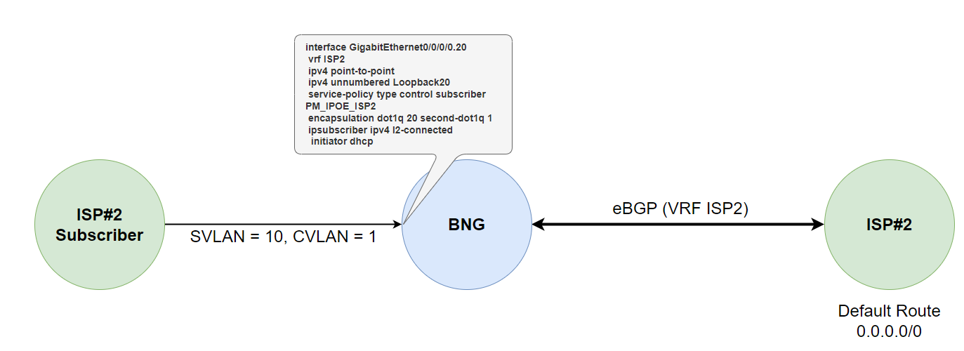
In part 2 we will setup a FreeRADIUS server + MariaDB database to store ISP#2 user details and then setup a DHCP server to get retail ISP#1 up and running with their own DHCP server (running DHCP proxy on the BNG for VRF ISP1) and build a quick FastAPI application to allow both of these ISPs to add and remove user data in the shared database.