Short blog post diving straight into the technical parts. The base topology here is just a flat level-2 IS-IS IGP with Segment Routing enabled, prefix-sid configured on all loopbacks (Node SID) and 10.0.xy.x/24 & 2001:db8:xy::x/64 configured on p2p where x = lowest router # on the segment, y = highest router # on the segment, loopbacks = 10.255.255.x/32 & 2001:db8::x/128 where x = router # in hostname.
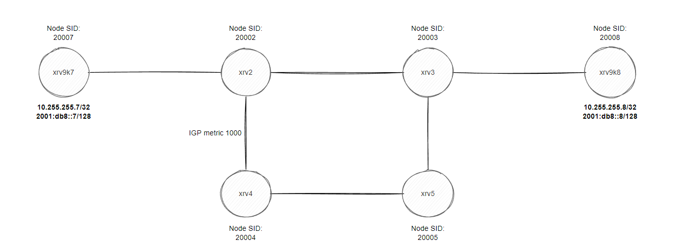
xrv2 and xrv3 are BGP route reflectors to all routers for ipv4/ipv6/vpnv4/vpnv6, xrv2 to xrv5 are all running the old IOS-XR virtual image (non 9k) so some commands might slightly be different, for example setting an affinity value on a link to “color” it. The reason for using affinity is purely for traffic engineering purpose, you assign a specific value (aka “color” the link) and then you can instruct various routers to avoid this “color” during the path computation (or explicitly use it! eg. setting all low latency links a specific color…). In this blog we will mainly be focusing on avoiding the “RED” service for VRF-B, whereas VRF-A we won’t touch and see what happens, I have purposely set a high metric between xrv2 and xrv4 to show that we can influence our router to not use this link unless instructed otherwise.
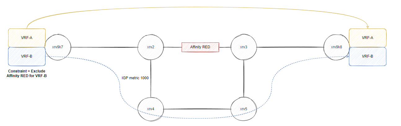
So our plan is to ensure VRF-B prefixes avoid the link between xrv2 and xrv3 without affecting the underlying routing decisions by changing metrics or using something like policy based routing. We want to program the path at the headend (xrv9k7 in this blog). Initial trace route from both VRFs take xrv2->xrv3->xrv9k8.
Setting the affinity between xrv2 and xrv3
We could normally set the affinity within the segment-routing -> traffic-eng configuration however XRv 6.3.1 syntax is slightly different, we enable this under the mpls traffic-eng configuration scope.
mpls traffic-eng
  affinity-map RED bit-position 23
  interface GigabitEthernet0/0/0/0
    attribute-names RED
If we take a look within the IS-IS database on xrv9k7 at the adjacency between xrv2 and xrv4, the default affinity is 0x00000000.
RP/0/RP0/CPU0:xrv9k7#show isis database verbose xrv2.00-00 detail
  <output ommited>
  Metric: 1000       IS-Extended xrv4.00
    Interface IPv6 Address: 2001:db8:24::2
    Neighbor IPv6 Address: 2001:db8:24::4
    Affinity: 0x00000000          <------- Default Affinity here
    Interface IP Address: 10.0.24.2
    Neighbor IP Address: 10.0.24.4
    Physical BW: 1000000 kbits/sec
    Reservable Global pool BW: 0 kbits/sec
    Global Pool BW Unreserved:
      [0]: 0        kbits/sec          [1]: 0        kbits/sec
      [2]: 0        kbits/sec          [3]: 0        kbits/sec
      [4]: 0        kbits/sec          [5]: 0        kbits/sec
      [6]: 0        kbits/sec          [7]: 0        kbits/sec
    Admin. Weight: 1000
    Ext Admin Group: Length: 32
      0x00000000   0x00000000
      0x00000000   0x00000000
      0x00000000   0x00000000
      0x00000000   0x00000000
    Link Maximum SID Depth:
      Label Imposition: 10
    ADJ-SID: F:0 B:0 V:1 L:1 S:0 P:0 weight:0 Adjacency-sid:24006
Whereas the adjaency between xrv2 and xrv3, affinity shows 0x00800000
RP/0/RP0/CPU0:xrv9k7#show isis database verbose xrv2.00-00 detail
  <output ommited>
  Metric: 100        IS-Extended xrv3.00
    Interface IPv6 Address: 2001:db8:23::2
    Neighbor IPv6 Address: 2001:db8:23::3
    Affinity: 0x00800000        <---- bit position 23
    Interface IP Address: 10.0.23.2
    Neighbor IP Address: 10.0.23.3
    Physical BW: 1000000 kbits/sec
    Reservable Global pool BW: 0 kbits/sec
    Global Pool BW Unreserved:
      [0]: 0        kbits/sec          [1]: 0        kbits/sec
      [2]: 0        kbits/sec          [3]: 0        kbits/sec
      [4]: 0        kbits/sec          [5]: 0        kbits/sec
      [6]: 0        kbits/sec          [7]: 0        kbits/sec
    Admin. Weight: 100
    Ext Admin Group: Length: 32
      0x00800000   0x00000000
      0x00000000   0x00000000
      0x00000000   0x00000000
      0x00000000   0x00000000
    Link Maximum SID Depth:
      Label Imposition: 10
    ADJ-SID: F:0 B:0 V:1 L:1 S:0 P:0 weight:0 Adjacency-sid:24004
Just a quick demo on this bit position, converted to binary:
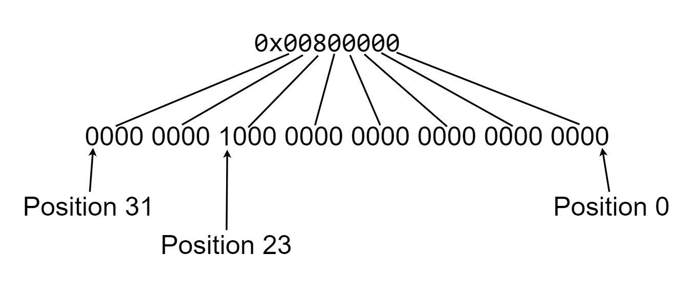
while the command says 0-255:
RP/0/0/CPU0:xrv2(config-mpls-te)#affinity-map RED bit-position ?
  <0-255>  Bit Position
if I configure any higher than bit position 31, the affinity is set as 0x00000000, I suspect probably the XRv version just uses 0-31 since this was the original amount defined in RFC5305 (for IS-IS), RFC7308 extends the original 32 admistrative groups (aka “colors”… I can’t type color without feeling wrong being British…). Even within the IS-IS database, you’ll see length of 32:
    Ext Admin Group: Length: 32
      0x00800000   0x00000000
      0x00000000   0x00000000
      0x00000000   0x00000000
      0x00000000   0x00000000
This process was repeated on xrv3 for G0/0/0/0…
L3VPN Configuration for VRF-B
Before we create a policy, we need to ensure that we can somehow tie a “color” to all the VRF-B prefixes and then we can use that color to automatically ensure we don’t go over the RED link between xrv2 and xrv3. This is why the affinity is typically referred as “coloring”.
Upon exporting the routes within the VRF, lets assign a route-policy to set the colour to 201 (SERVICE-BLUE we will call this). Prior to setting this, lets quickly take a look at 10.0.0.2/32 on xrv9k7 vpnv4 table for VRF-B RD:
RP/0/RP0/CPU0:xrv9k7#show bgp vpnv4 unicast rd 65420:2 10.0.0.2/32
Sat Jul  9 12:03:04.819 UTC
BGP routing table entry for 10.0.0.2/32, Route Distinguisher: 65420:2
Versions:
  Process           bRIB/RIB  SendTblVer
  Speaker                 23          23
Last Modified: Jul  9 12:02:41.412 for 00:00:23
Paths: (2 available, best #1)
  Not advertised to any peer
  Path #1: Received by speaker 0
  Not advertised to any peer
  Local
    10.255.255.8 (metric 300) from 10.255.255.2 (10.255.255.8)
      Received Label 24002
      Origin incomplete, metric 0, localpref 100, valid, internal, best, group-best, import-candidate, imported
      Received Path ID 0, Local Path ID 1, version 23
      Extended community: RT:65420:2
      Originator: 10.255.255.8, Cluster list: 10.255.255.2
      Source AFI: VPNv4 Unicast, Source VRF: VRF-B, Source Route Distinguisher: 65420:2
  <output ommited>
This looks like a traditional MPLS L3VPN at the moment, our service label is 24002, we can see the route target used for our import/exporting, everything looks normal if you’re used to MPLS L3VPN outputs. Lets assign that numeric value of 201 as a “color” and do a packet capture to see the BGP update.
On xrv9k8:
extcommunity-set opaque BLUE
  201
end-set
!
route-policy SET-COLOUR-BLUE
  set extcommunity color BLUE
  pass
end-policy
!
vrf VRF-B
 address-family ipv4 unicast
  export route-policy SET-COLOUR-BLUE
!
A lot of output is omitted like the BGP config, VRF config, you can find all the final configurations here: Configurations
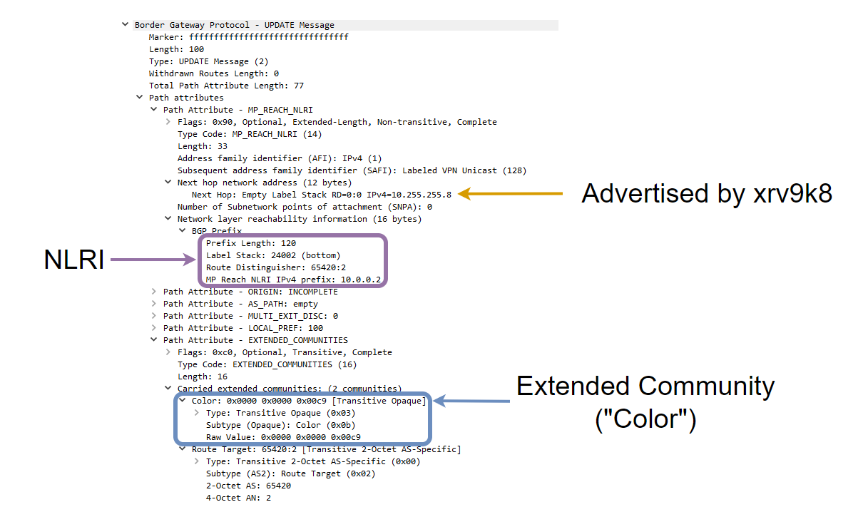
RP/0/RP0/CPU0:xrv9k7#show bgp vpnv4 unicast rd 65420:2 10.0.0.2/32
Sat Jul  9 12:12:53.403 UTC
BGP routing table entry for 10.0.0.2/32, Route Distinguisher: 65420:2
Versions:
  Process           bRIB/RIB  SendTblVer
  Speaker                 25          25
Last Modified: Jul  9 12:06:15.412 for 00:06:38
Paths: (2 available, best #1)
  Not advertised to any peer
  Path #1: Received by speaker 0
  Not advertised to any peer
  Local
    10.255.255.8 (metric 300) from 10.255.255.2 (10.255.255.8)
      Received Label 24002
      Origin incomplete, metric 0, localpref 100, valid, internal, best, group-best, import-candidate, imported
      Received Path ID 0, Local Path ID 1, version 25
      Extended community: Color:201 RT:65420:2     <-------- COLOR 201
      Originator: 10.255.255.8, Cluster list: 10.255.255.2
      Source AFI: VPNv4 Unicast, Source VRF: VRF-B, Source Route Distinguisher: 65420:2
  <output ommited>
Programming the SR-TE policy
We can typically offload this policy creation to an external server using PCE-PCEP but in this case, we will just manually define a policy on the headend router (xrv9k7) to always avoid links with the RED affinity (bit position 23) and this policy will always instantiate without the use of creating traffic engineering tunnels. So while this is still half-manual at traffic engineering, it avoids having us to build a quick server that speaks PCEP and we don’t have to distribute the link state info from IS-IS to a controller, that is beyond the scope of this blog… :(
Any VPNv4 prefix we learn with this color should dynamically build a path but avoid the RED link which is where SR-ODN shines. MPLS L3VPN customer routes from the SP point of view will always come from the loopback as a next-hop, this is typically how our traditional transport works with L3VPN services so if we can build the policy then it doesn’t matter which prefixes VRF-B customer advertised to our PE router, it should always avoid the RED link(s) configured in our TE topology.
Firstly, we create the affinity-map so we can reference it in our policy.
segment-routing
 traffic-eng
  affinity-map
   name RED bit-position 23
Now, we create the SR-ODN template policy for color 201 to match the BGP VPNv4 routes, dynamically build the LSP based on IGP metric (in this case the link between xrv2 and xrv4 is 1000 so this shouldn’t be preferred, but we will also configure a “constraint” which allows us to exclude any links in the network with the color RED). Now if we didn’t use SR-ODN, we would have to build the policy towards a specific endpoint like this
segment-routing
 traffic-eng
  policy SERVICE-BLUE
   color 201 end-point ipv4 10.255.255.8
   candidate-paths
    preference 10
     dynamic
      metric
       type igp
However, we can utilize ODN (On Demand Nexthop) so this policy automatically creates our SR-TE tunnels without having to define an end-point hence why it is “On Demand”.
segment-routing
 traffic-eng
  on-demand color 201
   dynamic
    metric
     type igp
    !
    affinity exclude-any             <----- Excluding any links that are configured with affinity 0x00800000 (bit position 23)
     name RED
    !
   !
  !
  affinity-map
   name RED bit-position 23
After this configuration, the policy is installed and up/up:
RP/0/RP0/CPU0:xrv9k7#show segment-routing traffic-eng policy
Sat Jul  9 12:36:20.030 UTC

SR-TE policy database
---------------------

Color: 201, End-point: 10.255.255.8
  Name: srte_c_201_ep_10.255.255.8
  Status:
    Admin: up  Operational: up for 00:06:37 (since Jul  9 12:29:42.576)
  Candidate-paths:
    Preference: 200 (BGP ODN) (active)
      Requested BSID: dynamic
      Constraints:
        Affinity:
          exclude-any:
          RED
        Maximum SID Depth: 10
      Dynamic (valid)
        Metric Type: IGP,   Path Accumulated Metric: 1400
          20002 [Prefix-SID, 10.255.255.2]
          24006 [Adjacency-SID, 10.0.24.2 - 10.0.24.4]
          20008 [Prefix-SID, 10.255.255.8]
    Preference: 100 (BGP ODN)
      Requested BSID: dynamic
      PCC info:
        Symbolic name: bgp_c_201_ep_10.255.255.8_discr_100
        PLSP-ID: 2
      Constraints:
        Affinity:
          exclude-any:
          RED
        Maximum SID Depth: 10
      Dynamic (pce) (invalid)
        Metric Type: NONE,   Path Accumulated Metric: 0
  Attributes:
    Binding SID: 24003
    Forward Class: Not Configured
    Steering labeled-services disabled: no
    Steering BGP disabled: no
    IPv6 caps enable: yes
Validating SR-TE ODN is working
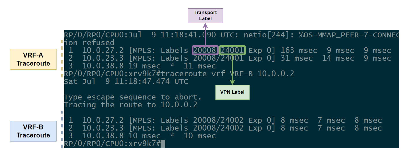
So how do we validate this? Firstly lets do a traceroute from VRF-A and VRF-B to see if VRF-B traffic towards 10.0.0.2/32 (xrv9k8) is not taking our best IGP path (xrv2->xrv3->xrv9k8) and then we will work backwards and dive into the segment routing control plane / mpls forwarding plane.
RP/0/RP0/CPU0:xrv9k7#traceroute vrf VRF-A 10.0.0.2
 1  10.0.27.2 [MPLS: Labels 20008/24001 Exp 0] 11 msec  8 msec  8 msec
 2  10.0.23.3 [MPLS: Labels 20008/24001 Exp 0] 9 msec  8 msec  8 msec
 3  10.0.38.8 14 msec  *  9 msec

RP/0/RP0/CPU0:xrv9k7#traceroute vrf VRF-B 10.0.0.2
 1  10.0.27.2 [MPLS: Labels 24006/20008/24002 Exp 0] 34 msec  16 msec  13 msec
 2  10.0.24.4 [MPLS: Labels 20008/24002 Exp 0] 15 msec  14 msec  16 msec
 3  10.0.45.5 [MPLS: Labels 20008/24002 Exp 0] 17 msec  14 msec  16 msec
 4  10.0.35.3 [MPLS: Labels 20008/24002 Exp 0] 13 msec  13 msec  17 msec
 5  10.0.38.8 18 msec  *  23 msec
Our first traceroute with VRF-A is our traditional MPLS L3VPN customer trying to get to xrv9k8 using the transport label of the loopback (20008 = prefix-sid configured on the loopback) and the underlying VPN service label to kick traffic into the VRF when it reaches the xrv9k8. However notice with the VRF-B traceroute, we see an additional label added on the label stack, 24006… 24000+ on IOS-XR are dynamic allocated labels so let’s dive into what this label actually is.
RP/0/RP0/CPU0:xrv9k7#show segment-routing traffic-eng policy
Sat Jul  9 12:43:49.760 UTC

SR-TE policy database
---------------------

Color: 201, End-point: 10.255.255.8
  Name: srte_c_201_ep_10.255.255.8
  Status:
    Admin: up  Operational: up for 00:14:07 (since Jul  9 12:29:42.576)
  Candidate-paths:
    Preference: 200 (BGP ODN) (active)
      Requested BSID: dynamic             <------ What is a BSID??
      Constraints:
        Affinity:
          exclude-any:
          RED
        Maximum SID Depth: 10
      Dynamic (valid)
        Metric Type: IGP,   Path Accumulated Metric: 1400
          20002 [Prefix-SID, 10.255.255.2]
          24006 [Adjacency-SID, 10.0.24.2 - 10.0.24.4]
          20008 [Prefix-SID, 10.255.255.8]
    Preference: 100 (BGP ODN)
      Requested BSID: dynamic
      PCC info:
        Symbolic name: bgp_c_201_ep_10.255.255.8_discr_100
        PLSP-ID: 2
      Constraints:
        Affinity:
          exclude-any:
          RED
        Maximum SID Depth: 10
      Dynamic (pce) (invalid)
        Metric Type: NONE,   Path Accumulated Metric: 0
  Attributes:
    Binding SID: 24003          <-------- This is interesting
    Forward Class: Not Configured
    Steering labeled-services disabled: no
    Steering BGP disabled: no
    IPv6 caps enable: yes
I’ve highlighted 2 key areas that are interesting, request BSID and the actual Binding SID. When we perform traffic engineering, SR-TE allocates a BSID on a per-policy basis, the main reasons for the BSID are scalability and compression. Some platforms have trouble with large label stacks and its just horrible to have an 8 label stack when you can replace those 8 labels with a single label to steer traffic into a specific SR-TE policy. BSIDs in terms of scalability can be assosicated across multiple domains to help steer traffic across inter-domain networks and essentially building that end to end LSP which would break in the typical segmented (unified-mpls like) network.
If we take a look at this BSID forwarding information, we will see the true label stack (since viewing the CEF table would not reflect this policy, it only reflects the BSID as below:
RP/0/RP0/CPU0:xrv9k7#show cef vrf VRF-B 10.0.0.2/32
10.0.0.2/32, version 19, internal 0x5000001 0x30 (ptr 0xd901620) [1], 0x0 (0xe249d50), 0xa08 (0xe74e570)
 Updated Jul  9 12:29:42.599
 Prefix Len 32, traffic index 0, precedence n/a, priority 3
   via local-label 24003, 3 dependencies, recursive [flags 0x6000]
    path-idx 0 NHID 0x0 [0xda48ab0 0x0]
    recursion-via-label
    next hop VRF - 'default', table - 0xe0000000
    next hop via 24003/0/21        <-------- 24003 is the BSID for this SR-TE policy
     next hop srte_c_201_e labels imposed {ImplNull 24002
The BSID forwarding information is where the real deal is:
RP/0/RP0/CPU0:xrv9k7#show segment-routing traffic-eng forwarding policy binding-sid 24003
Sat Jul  9 12:51:04.788 UTC

SR-TE Policy Forwarding database
--------------------------------

Color: 201, End-point: 10.255.255.8
  Name: srte_c_201_ep_10.255.255.8
  Binding SID: 24003
  Active LSP:
    Candidate path:
      Preference: 200 (BGP ODN)
    Local label: 24008
    Segment lists:
      SL[0]:
        Name: dynamic
        Packets/Bytes Switched: 15/480
        Paths:
          Path[0]:
            Outgoing Label: 24006
            Outgoing Interface: GigabitEthernet0/0/0/0
            Next Hop: 10.0.27.2
            Switched Packets/Bytes: 15/480
            FRR Pure Backup: No
            ECMP/LFA Backup: No
            Label Stack (Top -> Bottom): { 24006, 20008 }             <--------- the original transport label 20008 however we also see 24006

  Policy Packets/Bytes Switched: 15/480
In this case, our label stack should show 24006/20008(Transport)/24002(VPN). Below is a packet capture on xrv9k7 G0/0/0/0.
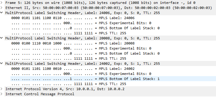
We can take a look at what xrv2 will do when they recieve this top label of 24006.
RP/0/0/CPU0:xrv2#show mpls forwarding labels 24006
Sat Jul  9 12:04:43.671 UTC
Local  Outgoing    Prefix             Outgoing     Next Hop        Bytes
Label  Label       or ID              Interface                    Switched
------ ----------- ------------------ ------------ --------------- ------------
24006  Pop         SR Adj (idx 3)     Gi0/0/0/1    10.0.24.4       4032
xrv2 will pop the label and send out to G0/0/0/1, which by this point will then follow xrv4->xrv5->xrv3 and look like our traditional Transport+VPN label. The transport label will be popped off at xrv3 due to the implicit null and exposes the VPN label so when the ICMP request finally reaches xrv9k8, they can push it into the VRF due to the local VPN label assosicated with that BGP vpnv4 prefix.
Essentially what our SR-TE policy has done is utilized the topology to find the best path avoiding the RED service by using the local adjacency SID xrv2 has advertised to xrv9k7 to go directly to xrv4, which solves our scenario where we want to avoid g0/0/0/0 on xrv2 due to the Affinity. if we now replace L3VPN with L2VPN/EVPN, the configuration is almost the same with the exception of working with EVI/xconnect groups by assosicating the SR-TE policy with the EVI/xconnect pw-classes and we can achieve EVPN/L2VPN with SR-TE BGP ODN.
While I haven’t actually tested this in EVPN on IOS-XRv9K (you can fake the dataplane working with injecting local mac addresses), I can’t see any reason why this wouldn’t work on the control plane within a lab as long as you use the 9K and not the old 32bit IOS-XRv image which barely supports these technologies.
Resources I used:
https://www.cisco.com/c/en/us/td/docs/iosxr/ncs5xx/segment-routing/63x/b-segment-routing-cg-63x-ncs540/b-segment-routing-cg-63x-ncs540_chapter_0110.html#id_125526
https://www.cisco.com/c/en/us/td/docs/routers/asr9000/software/asr9k-r7-0/lxvpn/configuration/guide/b-l2vpn-cg-asr9000-70x/b-l2vpn-cg-asr9000-70x_chapter_01101.html#concept_E054E3C768064F1F86B0430BAF6F722B
http://www.mplsvpn.info/2020/05/segment-routing-on-demand-next-hop-for.html
https://datatracker.ietf.org/doc/html/rfc5305#section-3.1
https://datatracker.ietf.org/doc/html/rfc7308
http://ops.openconfig.net/branches/models/master/docs/openconfig-network-instance-srte-policy.html